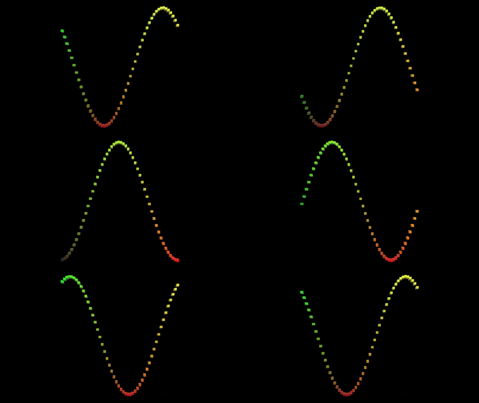
今天我们要实现的东西,就是下面这个动图的效果。使用代码控制方块的坐标,来展示 Sin 函数。方块的颜色变化,是随着坐标变化而动态改变的,我们会写一个超简单的 Shader 来实现。

接下来,我们一步一步实现。
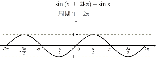
我们先来分析一下这个效果,把问题拆成一个一个小问题,然后逐个解决掉。我们先来考虑一下 Sin 函数的样子,看下面的图

Sin 函数是一个周期函数,也就是说,按照一定的长度去将这个图形切成一段一段的,那每一段都是相同的,而这个长度,就是2π。就像上图中的从 -π 到 π 就是一个周期。假设我们把这条 Sin 函数的曲线看成由一个个很小的点连起来构成的,而每一个点的位置,可以表示成 (x, y),很明显,x 的范围就是 [-π , π],而每一个点 y 的值是由 Sin(x) 算出来的。
那如何让曲线动起来呢?只要 x 的值不断地加上时间增量,就可以了。我们直接来看下代码,注意代码里的注释。
using System.Collections;
using System.Collections.Generic;
using UnityEngine;

public class Graph : MonoBehaviour
{
    // 建立一个 Cube
    public Transform pointPrefab;

    // 设定一个值,表示要用多少个 Cube 表示出这条曲线来,值越大,点就越细
    [Range(10, 100)]
    public int resolution = 10;

    private Transform[] points;

    private void Awake()
    {
        // 求出步长,相当于每一个 cube 的 x 轴相距多远
        float step = 2f / resolution;

        // 缩放一个 Cube
        Vector3 scale = Vector3.one * step;

        Vector3 position;
        position.y = 0;
        position.z = 0f;

        points = new Transform[resolution];
        for(int i = 0; i < resolution; ++i)
        {
            Transform point = Instantiate(pointPrefab);
            // 将 x 轴限制在 [-1, 1] 之间,这里 + 0.5是偏移半个方块
            position.x = (i + 0.5f) * step - 1f;
            point.localPosition = position;
            point.localScale = scale;
            point.SetParent(transform, false);
            points[i] = point;
        }
    }

    private void Update()
    {
        for(int i = 0; i < points.Length; ++i)
        {
            Transform point = points[i];
            Vector3 position = point.localPosition;

            // 每个方块的 x 轴是确定的,y 轴的计算就是不断地用 x 轴坐标加上时间增量,
            // 来做到周期移动的效果。这里之乘以 Mathf.PI 是为了将整个图像压缩在一定范围
            position.y = Mathf.Sin((position.x + Time.time) * Mathf.PI);
            point.localPosition = position;
        }
    }
}
建立一个 Cube,做成 Prefab,在场景中建立一个空物体,坐标归0,然后挂上上面的脚本。将 Prefab 拖到脚本的变量上,然后运行即可看到效果。
下面再来说一下如何动态改变颜色。颜色的变化,文章开始的图片中的颜色是由点的坐标位置决定的。坐标 x 值决定颜色的 r 通道,坐标 y 值决定颜色的 g 通道。所以,在 Shader 中首先要知道方块的坐标,然后坐标 x,y 值后,就可以设定颜色。(先写一个 Shader,然后新建一个 Material,并且使用我们写的 Shader,然后将 Material 赋予 Cube 的 Prefab)
注意:对于 Shader 来说 ,INPUT 结构中的 worldPos 是方块每一个顶点的位置
o.Albedo.rg = IN.worldPos.xy * 0.5 + 0.5; 这一句就是根据坐标值设定颜色的 Shader 代码。这里为什么要乘 0.5 加 0.5 呢?因为上面的C#代码中,我们将每一个 Cube 的位置设置为了[-1, 1]之间,但是颜色的值不能为负,所以这里的乘 0.5 加 0.5 其实就是将坐标值映射为 [0, 1] 之间,从而作为颜色值来用。
下面的 Shader 代码是在 Unity 2018 中新建一个 Surface Shader,然后删除里面一些不必要的代码,然后添加我们自己的代码,大部分都是 Unity 自己生成的,大家可以对比一下不同。
Shader "Custom/ColoredPoint"
{
    Properties
    {
        _Glossiness ("Smoothness", Range(0,1)) = 0.5
        _Metallic ("Metallic", Range(0,1)) = 0.0
    }
    SubShader
    {
        Tags { "RenderType"="Opaque" }
        LOD 200

        CGPROGRAM
        // Physically based Standard lighting model, and enable shadows on all light types
        #pragma surface surf Standard fullforwardshadows

        // Use shader model 3.0 target, to get nicer looking lighting
        #pragma target 3.0

        struct Input
        {
            // 这一句是我们自己写的
            float3 worldPos;
        };

        half _Glossiness;
        half _Metallic;

        // Add instancing support for this shader. You need to check 'Enable Instancing' on materials that use the shader.
        // See https://docs.unity3d.com/Manual/GPUInstancing.html for more information about instancing.
        // #pragma instancing_options assumeuniformscaling
        UNITY_INSTANCING_BUFFER_START(Props)
            // put more per-instance properties here
        UNITY_INSTANCING_BUFFER_END(Props)

        void surf (Input IN, inout SurfaceOutputStandard o)
        {
            // 这一句也是我们自己写的
            o.Albedo.rg = IN.worldPos.xy * 0.5 + 0.5;

            // Metallic and smoothness come from slider variables
            o.Metallic = _Metallic;
            o.Smoothness = _Glossiness;

            // 这一句也是我们自己写的
            o.Alpha = 1;
        }
        ENDCG
    }
    FallBack "Diffuse"
}
现在再次运行一下,是不是已经做到了文章一开始的那个图的效果。